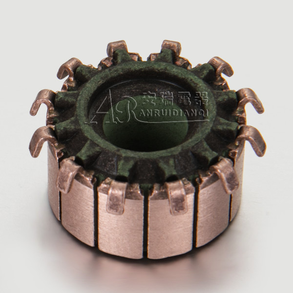
The motor commutator is a component of a DC permanent magnet series motor in order to keep the motor rotating. Structurally, the motor commutator is a circle with several contact pieces connected to each contact on the rotor. The two electrodes connected outside are called brushes to contact with it, and only contact two of them at the same time. The principle of the motor commutator is that when the coil passes the current, it will be rotated by the attraction and repulsion force under the action of the magnet. When it turns to balance with the magnet, the originally energized wire will be compared to the corresponding motor commutator. The contact piece is separated from the brush, and the brush is connected to the contact piece corresponding to the set of coils that produces the driving force, so that the DC motor will start to rotate after repeating.
The motor commutator and the brush form a corresponding sliding friction pair in the motor. The influence of the motor commutator on the performance of the motor is mainly determined by the high-speed sliding of the brush under the conditions (electric load, contact pressure, environmental conditions, etc.) Electrical contact behavior. In addition to transmitting the longitudinal current when the motor commutator works, there is also a current commutation task performed in the short-circuit armature coil. These currents are the reverse current and reactance voltage generated during the main current motor commutator, which causes edge sparks and arcs when the brushes slide on the surface of the motor commutator. The influence of the motor commutator on the performance of the motor depends on the process of achieving circuit conduction when it slides with the brushes at a relatively high speed under the conditions. Although the description of this process is complicated and theoretical research is still under development, through a comparative analysis of the operating conditions of micromotors, it can be determined that wear is a key factor leading to changes in contact resistance.
The motor commutator of a DC motor refers to the rotating armature winding element, the process of changing the direction of the current in the element when passing through the brush from one branch to another branch. In the process of changing the direction of current, a spark is generally generated between the brush and the motor commutator, which is the main reason for the difficulty and failure of the motor commutator. Therefore, the standard divides the motor into several levels (1, 5/4, 3/2, 2, 3) according to the spark size when commutation. For continuous working DC motors, the sparks of the motor commutator should not exceed 3/2. The DC motor for electric bicycles is a continuous working motor and should meet the requirements of no more than 3/2 sparks. The standard stipulates: When the spark is level 3/2, most or all of the brush edges have weak sparks, so there are black marks on the motor commutator, but it will not continue to develop. It can be removed by rubbing the surface with gasoline. There are slight burn marks on the brush, which will not affect the continuous and normal operation of the motor.