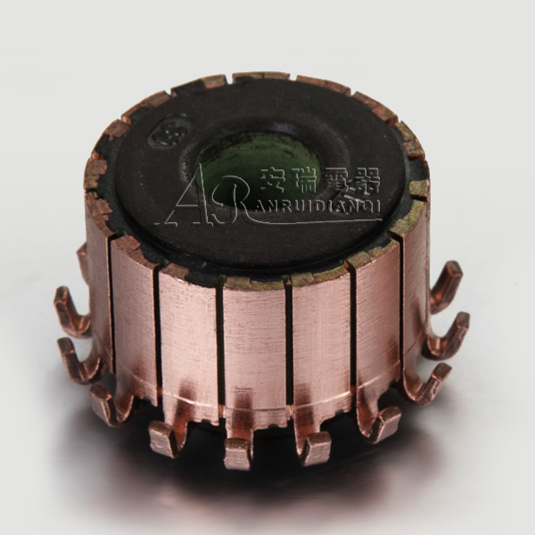

The integral type DC motor commutator includes a pressing ring, a commutator piece assembly, and a sleeve. The commutator piece assembly is an integral structure formed by pressing an integral commutator piece with a raised piece on it. Compared with the commutator of the existing large-scale DC motor, the utility model adopts an integrated commutator, that is, the commutator with the riser is integrally stamped, which overcomes the difference between the riser and Problems caused by the welding of commutator segments. The commutator is provided with grooves at a distance from the working surface where the commutator segments are assembled, and a weft-free belt is bound in the grooves. Through this structure, the deformation of the commutator is controlled within the specified range to ensure the reliable operation of the motor. The integral commutator structure of the large-scale DC motor of the utility model is reasonable, and the operation of the DC motor can be reliable.
If you want to keep the electromagnetic torque at the original value, you must change the slip rate of the motor to change the stator electromotive force, so that the secondary current basically returns to the original value. This means that the speed has changed. If the additional electromotive force is in phase with the stator electromotive force through the adjustment of the brush position, the speed will increase. If the brushes are adjusted to make the commutator electromotive force and the stator electromotive force anti-phase, the speed will drop. The rotor winding with slip ring is passed through the three-phase alternating current to generate the air gap magnetic field of the motor, which rolls at the synchronous speed пs relative to the rotor. If the rotor itself rolls in the reverse direction at the speed п, the speed of the magnetic field relative to each branch of the stator and the commutator winding is the slip speed, so the electromotive force induced in the stator winding and the commutator winding is also the slip frequency. It changes with the slip rate. However, the magnetic field has a fixed relative speed to the rotor (synchronous speed пs), so the magnitude of the commutator winding electromotive force has nothing to do with the slip. The three-phase parallel commutator motor is actually commensurate with the asynchronous motor with the external electromotive force of the slip frequency (ie the electromotive force of the commutator winding) in the secondary winding (ie the stator a, b, and c windings). The only difference is that the former is placed on the rotor on the primary side and the secondary side on the stator.
The speed adjustment of the electric idea is realized by adjusting the opening angle of the brush 2β. The adjustment of the power factor is realized by moving the three pairs of brushes at the same time to change the relative position of the three stator windings. If the opening angle of the brush 2β is adjusted to zero, the electromotive force applied to the secondary side is zero. At this time, it is the same as the general three-phase asynchronous electric concept. When the 2β tension is a non-zero angle, additional electromotive force is added to the secondary side. The addition of additional electromotive force changes the total electromotive force and current of the secondary loop.
